Hello all, finally finished with my implementation of an Arduino based weather station and associated Observing Conditions Driver. The driver also writes out a boltwood oneline file which can be used with Chris’ Safety monitor driver.
Detailed build instructions and installers for the driver and a Weatherstation app.
Thanks! All the solutions out there seemed very pricey for what seems like really simple hardware and fairly simple software. So decided to give it a shot. Turned out pretty well and in testing so far seems reliable and useful.
I only hope others find it useful and build one as well. The hardware itself, once all the parts are on hand, takes only an hour or so. Software took longer, but now everyone has that with 0 time investment. All parts cost me ~$150.
I also built an Arduino version and ASCOM driver. I left off the wind guage.
I wish I had placed some tiny heat source under my raindrop detector. I have about 90 feet of nichrome wire leftover from my dew heater project and figure that I could slap a 100ohm resistor and an inch of nichrome to provide the microdegree of heat to prevent dew from forming on it. I also wish that I had included an RF transmitter so I could remote a klaxon in my bedroom in case that thing detects rain while I’m asleep.
That said, there was something I want to try with the driver. I know enough C# to be dangerous. Is there any reason I can’t also implement SafetyMonitor in the same code so I can integrate the two devices into one com port? I’d really like to tie my sky temperature and raindrop detector into SGP.
Honestly, I also want SGP to start sounding alarms if Rain goes over a very very low threshold but, that’s not my call to make.
I am also thinking of adding a small 1k resistor to generate some heat internally. There is just a little bit of fogging on the window really cold nights. But not enough of a problem right now to warrant a solution.
On the OC driver doubling as a Safety Monitor Driver. I am not sure that would work within the COM model. Sure, we could have the driver implement both interfaces, but the software package using it will have to know that both drivers are one and the same and hence not instantiate multiple instances (Because then you will have clashes on the hardware resources). And even if that was true, it will then have to cast the object or make SafetyMonitor calls on a OC object. This would break if someone is indeed using two separate drivers.
In fact if you look the OCH it does something similar, you can specify the driver for each sensor, but in the code it goes through the instruments to make sure it is only instantiating one instance of an object.
Just my 2c anyways. Maybe it can be done, but my initial feeling is that it is not, at least not in a scalable way.
The ASCOM Local Server template is designed to allow multiple connections and multiple drivers to connect to the same hardware. The LocalServer exe provides shared resources - which could be a serial port or the entire hardware connection. All instances of the driver DLL connect to the shared resources. It also handles conversion between 32 and 64 bit drivers and applications.
It’s not the most trivial of things to set up though and for Observing Conditions and Safety monitor using the Boltwood text file may be simpler.
Hey all, sorry for the long silence. Got some more spare time and I did a few changes:
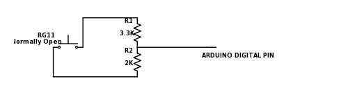
Integrate a Hydreon RG11 for rain detection (configured through dip switches in “It’s Raining” mode). Fairly simple integration, ground is tied to arduino ground and NO is connected a digital input pin. Only caveat is that, since the RG11 is a 12v system, you need to voltage divide it so the input pin is getting 5v. I used 2k and 3.3k resistors. The circuit is:
Also replaced the breadboard with a stackable protoshield so things are cleaner inside the box.
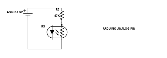
HDS10 sensor for condensation detection. Although I am not sure how useful this piece is given RG11. This behaves as a photoresistor and so the circuit is:
All the relevant sketch changes and some minor changes to the ascom driver to incorporate is not up on github as well.
Oh! I forgot another change I did. Wanted to simplify the cables running into the box. So I soldered a HC-06 module to the RX and TX pins. Lots of documentation online so I am sure you will figure it out, but two things to take care of:
Level shift the RX pin on HC-06, since these modules operate at 3.3v but arduino is output 5v on the TX pin. Again this is a simple voltage divide. I, again used 2k and 3.3k resistors, except the R1 and R2 is swapped.
In my case the version of HC-06 I had also needed a pullup resistor on the TX pin of the module since the voltage levels seemed to be reversed (Arduino expects idle voltage on the RX line to be 5v)
So now I can connect from my laptop to the weather station over bluetooth serial (shows up as a COM port) and I only have to run a 12v line to the box which is powering both the arduino itself and the RG11. The 12v supply is going through a relay controlled by photon (just like all my other power system. Can also be controlled via IFTTT and VB scripts for easy integration into your phone or into SGP etc.) so weather station can be brought online remotely and connected remotely as well.
I just recently completed a similar Arduino project using a bme280 sensor and Anemo anemometer together with an ethernet shield. It was a Valentine’s day gift for the wife and is working well. I had to use ethernet due to the distance involved and not being familiar with bluetooth. I will be building a separate weatherstation that will also incorporate cloud and lightening detection. AstroGabe on CN has described his weather station using wireless esp 6822.
Does your project feature a sleep mode? I haven’t gotten into the code sketch yet as I just started to learn about Arduino a couple of months ago. I really like the illustrations you have in the pdf and how you have incorporated the ascom platform into this project.
I do have a concern about the voltage divider for the 12volts. What is the current draw to the arduino from this divider?
Other than that, it looks like a great project and congrats to you.
I have not measured the current draw but it should be 40mA which is what
all digital pins draw. The rg11 is just acting as a relay with the relay
being triggered on rain drop detection. The relay is rated for a max of
1amp. But the actual current draw will be whatever the load draws, which in
this case is the digital pin which should draw 40mA.
Or am I understanding your question wrong?
On cloud detection, the whole point of incorporating a melexis 90614 is to
do cloud detection using the difference in ambient and sky temp. Seems to
work pretty reliably for me once configured.
Lighting detection is something I didn’t bother with given California, but
feel free to extend what I wrote.
You understand corectly. Current draw is low. The cloud detection scheme and the device you are using is different from what I’ve seen elsewhere. Yours looks to be a better mouse trap. Again, thank you for making this available.
The main thing I looked for in selecting those resistors was the power in
the resistors to make sure they don’t melt. At a total resistance of 5.3k
and 12v (the input pin is not configured in pullup mode and hence presents
some 100 megohm impedance), the current will be ~2.6mA. The power, then, on
each resistor is < 0.022w which is way below the power rating of 1/8watt.
Nothing is cooked yet and things have been running continuously for a day
or two now…so far so good
Have fun Jim. Once you have the parts, it should literally only take a few hours to solder and assemble everything and the total cost should not go above 150 (if that).
Just received the hydreon so I’ll be slicing and dicing your code for the rain gauge to my ethernet configuration. I really appreciate the ascom write up of your project. It was very helpful. You did a nice job of illustrating and documenting this project.
Awesome! Keep us posted on your weatherstation. Ethernet/Wifi is something that I thought about, but that meant changing up the connection code in the Ascom driver. Usually router leases on IPs won’t change on subsequent renewal, but there is always a possibility that it will change making it even harder without some sort of discovery protocol. Being lazy, I just opted for the simple reliable COM port which will be the same through repeated use once bound
Also on the sleep mode, using sleep mode on Arduino implies using pins 2 and 3 for interrupts to wake up. Pins 2 and 3 are already used on the weather shield for Wind and Rain. While rain might not interrupt often (except when it’s raining), Wind will almost certainly make any sleep mode irrelevant. Complicating matters further is clock maintenance. Clock, I believe, is frozen when going to sleep and on subsequent resume, the counts might all be wrong (in terms of the way rain is being tallied up and a few other things). So just didn’t mess with it.
In my case, I opted instead to just wire the whole thing through a relay controlled by a photon (everything else is as well, like the scope, dome, mount etc.) and have VB scripts around the photon (which is all REST based). So the weather station is turned on whenever I start a sequence and turned off when the sequence ends with start and end scripts that I have (the start and end scripts also turn on/off the other equipment in order, like mount before dome, etc.)
Thank you very much for sharing this great project!
Do you think is it possible to start with just the weather shield and cloud sensor with MLX90614 without the weather meter (half of the project costs)? Is the software compatible with this configuration?
Absolutely. The software will still read the rain, wind and wind pins, but
they will not make any sense since they are open and floating. So just
don’t rely on those readings or values