I think your analysis is flawed in that you seem to be saying that no matter the gain the maximum output is 4096. The graphs for the chip clearly show that when the gain goes up the dynamic range goes down - that is fewer bits are involved. If the gain did not change the dynamic range then your analysis would be correct but that is not the case.
I also have one of these cameras, but never really fully understood until now what the relationship was between gain and dynamic range. Thank you!
I have yet to truly parse the relationship between gain and detail, but I am optimistic that if I re-read this thread a few times I will.
Also, I’ll set my gain back from zero to 139. 
Maybe that will be useful :
The maximum output is always 4095 because the analog to digital converter is a 12 bit device and this is its highest reading (2 to the power of 12. SGP or the camera driver scale this up to 16 bits and therefore a max of 65,535). Have a look at the block diagram of the chip, everything before the analog to digital converter is just a voltage that is amplified (scaled). So, when you have a gain setting of 50, this is defined in the chip as a voltage gain of 5 dB, so it is equal to a scaling of 1.778 times the voltage on the picture element (pixel). It works out that when 11,410 electrons are on the pixel you will have reached the maximum voltage coming out of the amplifier that the A/D converter will max out and give a maximum count of 4095. The pixel isn’t full because we know it can hold more than 20,000 electrons before reaching the max voltage the chip can handle, but calculating back from the max voltage we only need 11,410 electrons to saturate the output of the amplifier, so it will also saturate the A/D and we see the resulting pixel in the image as the maximum value of 4095. If the gain was set to zero then the A/D will be saturated when there are 20,290 electrons on the pixel. The output of the A/D is still a count of 4095, but it took more electrons to get there due to the lower amplifier gain. You obtain a higher dynamic range by selecting a lower gain in the voltage amplifier before the digital conversion. The charts provided by ZWO are very easily calculated and there is nothing they have done that doesn’t follow this logic. The charts they provide are not results measured in a laboratory.
Your dynamic range is not the range of bits or counts. It is the range of photons captured before this reading maxes out.
I need to think more about what others are saying about noise being lower at lower gain. While that is true, noise in the technical sense when using A/D converters doesn’t just come from the analog side, it also comes from the digital conversion introducing steps in the output, or adding granularity where the signal has none. I have analysed the ZWO charts to see if they make sense, but not in this way. I suspect when the step issue discussed in my 4 pixel image above is taken into account the noise is actually lower in the gain=139 case.
Let’s not confuse the 12 bit A to D as meaning that we have 12 bits of real data. With a gain of 139 there is 11 meaningful bits of data because of the reduce dynamic range. At a gain 50 there is 12 bits of meaningful data. You are getting hung up on the belief that unity gain has better accuracy but it is not the case because of the reduced dynamic range. At a gain of 50 we have to increase the exposure about three times over the 139
gain to achieve a near saturated image in both cases. The increased exposure means 3 photons for each 1 photon for 139 gain. The longer exposure (more photons) is making up for the fact that we can’t distinguish single photons. If we were to use the same exposure for both 50 and 139 gain then the 139 gain would be fine because the 50 gain is under exposed and not utilizing all the dynamic range. The increase dynamic range at 50 gain is only a win if you have a long enough exposure to use the full dynamic range.
The point being there is no magic sweet spot at 139 (unity) gain. It all depends on the exposure time for which you need to consider other issues like guiding errors and amp glow. If you can manage a long enough exposure at 50 gain to achieve a near saturated image then that will be your best image accuracy. With a dim target and narrow band filters, this ideal exposure is likely out of reach so a higher gain makes sense because you can’t achieve the maximum dynamic range with the less than ideal exposure.
I will take a guess here that you are referring to this chart by ZWO when you say the camera is only 11 bits at a gain of 139 and 12 bits at a gain of 50
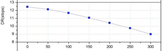
This is actually referring to dynamic range in the language normally set aside for those ancient cameras that used film. In this instance a dynamic range in “stops” simply gives you an indication of the difference between the brightest and the darkest parts of the image it can record. It has nothing to do with bits or bit depth. It is also a relative measure that allows you to compare different camera settings, so all you can tell from this is that with Gain=139 the number is 11.1 stops and at Gain=50 the number is 12 stops. Therefore at Gain=50 the camera will record just under twice the range of dark to light (each stop is double).
We can actually calculate what it really is from the other charts such as the full well depth chart
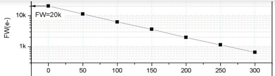
This tells us that the electrons are 11.4k and 4.1k for the 50 and 139 cases. This means that the true dynamic range difference between these settings is 2.79, or almost 1.4 stops, not just under 1.
What it means is the lower bit (in the 11 stop case) is not meaningful. The camera is not stretching the 11 stop dynamic range into 12 bits. Rather the result is mapped to the 11 high bits.
Again, given near saturation exposures, the 50 gain is going to have more dynamic range than the 139 gain. The graph clearly shows that. Your premise that 139 (unity) gain is the ideal setting is just not the case. In choosing the gain, one must consider the subject, equipment limitations and exposure time.
Out of curiosity, how do you explain the chart showing the Gain=0 case being 12.5 bits
The chart actually says the dynamic range is 12.5 stops which I suppose is mapped to 12 bits by discarding a half a stop.